はじめに
スプラトゥーンってどうやって実装しているだろう?と思って調べていたら、以下の記事を見つけました。
あれは3Dに見えるけど、処理上では、 「3Dを2D(UVマップ)に逆変換して"塗り絵"をするアプリ」だった。
【マジか】『スプラトゥーン』に隠された技術的な秘密が解析でついに判明!! 「スプラは3Dに見えるけど、実は○○だったwwww」 : はちま起稿
ライトマップを使ったら出来るかも、と思って作ってみました。
やること
プロジェクターで投影したインクをライトマップのuv位置に書き込めたらそれっぽくなりそうです。uv位置に書き込む方法は以下の記事がとても参考になりました。
- 適当にライトマップを焼く
- プロジェクターを自作する
- プロジェクションした結果をライトマップのuvに書き込む
- いい感じに表示する
適当にライトマップを焼く


プロジェクターを自作する
unityのプロジェクターを使えればよかったのですが、このあとの処理でレンダリング先を変更する必要があるので作ってみます。
using System.Collections;
using System.Linq;
using System.Collections.Generic;
using UnityEngine;

[ExecuteInEditMode]
public class MyProjector : MonoBehaviour
{
    // 視錐台計算用のカメラ。描画はしない
    [SerializeField]
    Camera m_Camera;

    // プロジェクター用マテリアル
    [SerializeField]
    Material m_Material;

    private void Start()
    {
        // 正方形にする
        m_Camera.aspect = 1f;
    }

    private void Update()
    {
        UpdateInput();
    }

    void UpdateInput()
    {
        // レイの当たったところにプロジェクションする
        var ray = Camera.main.ScreenPointToRay(Input.mousePosition);
        if (Physics.Raycast(ray, out var hit))
        {
            transform.forward = -hit.normal;
            transform.position = hit.point + hit.normal * 3;
        }
    }

    private void OnRenderObject()
    {
        Rendering();
    }

    void Rendering()
    {
        // OPTIMIZE: 視錐台と重なるレンダラーを探す
        var renderers = FindObjectsOfType<MeshRenderer>().ToList();
        var planes = GeometryUtility.CalculateFrustumPlanes(m_Camera);
        var targetRenderers = renderers.FindAll(x => GeometryUtility.TestPlanesAABB(planes, x.bounds));

        // プロジェクターから見たクリッピング空間に変換する用
        var projectionMatrix = GL.GetGPUProjectionMatrix(m_Camera.projectionMatrix, false);
        m_Material.SetMatrix("_ProjectorVP", (projectionMatrix * m_Camera.worldToCameraMatrix));

        foreach (var renderer in targetRenderers)
        {
            var filter = renderer.GetComponent<MeshFilter>();
            m_Material.SetPass(0);
            Graphics.DrawMeshNow(filter.mesh, renderer.localToWorldMatrix);
        }
    }
}
Shader "Unlit/Projector"
{
    Properties
    {
        _InkTex ("Texture", 2D) = "white" {}
    }
    SubShader
    {
        Tags { "RenderType"="Opaque" }
        ZWrite Off
        ColorMask RGB
        // アルファブレンド
        Blend SrcAlpha OneMinusSrcAlpha
        Offset -1, -1

        Pass
        {
            CGPROGRAM
            #pragma vertex vert
            #pragma fragment frag

            #include "UnityCG.cginc"

            struct appdata
            {
                float4 vertex : POSITION;
                float2 uv : TEXCOORD0;
                float2 uv2 : TEXCOORD1;
            };

            struct v2f
            {
                float4 uv : TEXCOORD0;
                float4 vertex : SV_POSITION;
            };

            sampler2D _InkTex;
            float4x4 _ProjectorVP;
            float4 projector_LightmapST;

            v2f vert (appdata v)
            {
                v2f o;
                o.vertex = UnityObjectToClipPos(v.vertex);
                o.uv = ComputeScreenPos(mul(mul(_ProjectorVP, unity_ObjectToWorld), v.vertex));
                return o;
            }

            fixed4 frag (v2f i) : SV_Target
            {
                fixed4 col = tex2Dproj(_InkTex, UNITY_PROJ_COORD(i.uv));

                // カメラの範囲外を除外
                float4 uv = i.uv / i.uv.w;
                fixed3 isOut = step((uv - 0.5) * sign(uv), 0.5);
                float alpha = isOut.x * isOut.y * isOut.z;

                return col * alpha;
            }
            ENDCG
        }
    }
}
note
        // OPTIMIZE: 視錐台と重なるレンダラーを探す
        var renderers = FindObjectsOfType<MeshRenderer>().ToList();
        var planes = GeometryUtility.CalculateFrustumPlanes(m_Camera);
        var targetRenderers = renderers.FindAll(x => GeometryUtility.TestPlanesAABB(planes, x.bounds));

...

        foreach (var renderer in targetRenderers)
        {
            var filter = renderer.GetComponent<MeshFilter>();
            m_Material.SetPass(0);
            Graphics.DrawMeshNow(filter.mesh, renderer.localToWorldMatrix);
        }
プロジェクターの視錐台と交差するレンダラーを探して、Graphics.DrawMeshNowで再度上からメッシュを描画します。この時にプロジェクションしたい画像を合成するイメージです。
        // プロジェクターから見たクリッピング空間に変換する用
        var projectionMatrix = GL.GetGPUProjectionMatrix(m_Camera.projectionMatrix, false);
        m_Material.SetMatrix("_ProjectorVP", projectionMatrix * m_Camera.worldToCameraMatrix);
            v2f vert (appdata v)
            {
                ...
                o.uv = ComputeScreenPos(mul(mul(_ProjectorVP, unity_ObjectToWorld), v.vertex));
                ...
            }
上記の処理を通るとプロジェクターの視錐台と交差している部分が、ちょうど0~1のuvを返すようになります。そのuvを使ってプロジェクションしたい画像を貼り付けます。詳しくは以下の記事が参考になりました。
やや雑ですが、ここまででプロジェクターができました。

追記
ComputeScreenPosを使っていましたが、ComputeScreenPosは内部で_ProjectionParamsを使っているため、今回のようにカメラを介さずに描画する時はうまくいかないかもしれません。
inline float4 ComputeNonStereoScreenPos(float4 pos)
{
    float4 o = pos * 0.5f;
    o.xy = float2(o.x, o.y * _ProjectionParams.x) + o.w;
    o.zw = pos.zw;
    return o;
}
プロジェクションした結果をライトマップのuvに書き込む
見てもらうと分かると思いますが、なんのことはない、頂点位置をたんにUV値にしているだけ、なんですね。(-1~1の間になるように補正はしていますが)
uv位置に書き込むのに悩みましたが、先に紹介した記事によるとかんたんにできるようです。頂点シェーダーに渡ってきたuvが0〜1になっているので、-1~1に変換したuv座標を頂点座標にしてあげればuvマッピングされた画像ができあがるようです。今回はuvをライトマップのuvに変換してからそれを行います。
using System.Collections;
using System.Linq;
using System.Collections.Generic;
using UnityEngine;

[ExecuteInEditMode]
public class MyProjector : MonoBehaviour
{
    // 視錐台計算用のカメラ。描画はしない
    [SerializeField]
    Camera m_Camera;

    // プロジェクター用マテリアル
    [SerializeField]
    Material m_Material;

    // 書き出し先
    [SerializeField]
    RenderTexture m_RenderTexture;

    // rに書き込むインク
    [SerializeField]
    Texture2D m_RedInkTexture;

    // gに書き込むインク
    [SerializeField]
    Texture2D m_GreenInkTexture;

    // 描画トリガー
    bool m_RenderingRequest;

    private void Start()
    {
        // レンダーテクスチャを初期化する
        RenderTexture tmp = RenderTexture.active;
        RenderTexture.active = m_RenderTexture;
        GL.Clear(true, true, Color.clear);
        RenderTexture.active = tmp;

        // 正方形にする
        m_Camera.aspect = 1f;
    }

    private void Update()
    {
        // 左クリックでrに書き込む
        if (Input.GetMouseButtonDown(0))
        {
            UpdateInput(m_RedInkTexture);
        }

        // 右クリックでgに書き込む
        if (Input.GetMouseButtonDown(1))
        {
            UpdateInput(m_GreenInkTexture);
        }
    }

    void UpdateInput(Texture2D inkTex)
    {
        // レイの当たったところにプロジェクションする
        var ray = Camera.main.ScreenPointToRay(Input.mousePosition);
        if (Physics.Raycast(ray, out var hit))
        {
            transform.forward = -hit.normal;
            transform.position = hit.point + hit.normal * 3;
            m_Material.SetTexture("_InkTex", inkTex);
            m_RenderingRequest = true;
        }
    }

    private void OnRenderObject()
    {
        // 描画トリガーがあれば
        if (m_RenderingRequest)
        {
            Rendering();
            m_RenderingRequest = false;
        }
    }

    void Rendering()
    {
        RenderTexture tmp = RenderTexture.active;
        RenderTexture.active = m_RenderTexture;

        // OPTIMIZE: 視錐台と重なるレンダラーを探す
        var renderers = FindObjectsOfType<MeshRenderer>().ToList();
        var planes = GeometryUtility.CalculateFrustumPlanes(m_Camera);
        var targetRenderers = renderers.FindAll(x => GeometryUtility.TestPlanesAABB(planes, x.bounds));

        // プロジェクターから見たクリッピング空間に変換する用
        var projectionMatrix = GL.GetGPUProjectionMatrix(m_Camera.projectionMatrix, false);
        m_Material.SetMatrix("_ProjectorVP", projectionMatrix * m_Camera.worldToCameraMatrix);

        foreach (var renderer in targetRenderers)
        {
            var filter = renderer.GetComponent<MeshFilter>();
            // ライトマップ用
            m_Material.SetVector("projector_LightmapST", renderer.lightmapScaleOffset);
            m_Material.SetPass(0);
            Graphics.DrawMeshNow(filter.mesh, renderer.localToWorldMatrix);
        }

        RenderTexture.active = tmp;
    }
}
Shader "Unlit/Projector"
{
    Properties
    {
        _InkTex ("Texture", 2D) = "white" {}
    }
    SubShader
    {
        Tags { "RenderType"="Opaque" }
        ZWrite Off
        ColorMask RGB
        // アルファブレンド
        Blend SrcAlpha OneMinusSrcAlpha
        Offset -1, -1

        Pass
        {
            CGPROGRAM
            #pragma vertex vert
            #pragma fragment frag

            #include "UnityCG.cginc"

            struct appdata
            {
                float4 vertex : POSITION;
                float2 uv : TEXCOORD0;
                float2 uv2 : TEXCOORD1;
            };

            struct v2f
            {
                float4 uv : TEXCOORD0;
                float4 vertex : SV_POSITION;
            };

            sampler2D _InkTex;
            float4x4 _ProjectorVP;
            float4 projector_LightmapST;

            v2f vert (appdata v)
            {
                v2f o;

                // ライトマップのuvに変換
                v.uv2 = v.uv2.xy * projector_LightmapST.xy + projector_LightmapST.zw;
                #if UNITY_UV_STARTS_AT_TOP
                    v.uv2.y = 1.0 - v.uv2.y;
                #endif

                // 頂点をuv座標にする
                o.vertex = float4(v.uv2 * 2.0 - 1.0, 0.0, 1.0);
                o.uv = ComputeScreenPos(mul(mul(_ProjectorVP, unity_ObjectToWorld), v.vertex));
                return o;
            }

            fixed4 frag (v2f i) : SV_Target
            {
                fixed4 col =  tex2Dproj(_InkTex, UNITY_PROJ_COORD(i.uv));
                float4 uv = i.uv / i.uv.w;

                fixed3 isOut = step((uv - 0.5) * sign(uv), 0.5);
                float alpha = isOut.x * isOut.y * isOut.z;

                return col * alpha;
            }
            ENDCG
        }
    }
}
note
    // rに書き込むインク
    [SerializeField]
    Texture2D m_RedInkTexture;

    // gに書き込むインク
    [SerializeField]
    Texture2D m_GreenInkTexture;
この画像を使ってクリックされるたびにrとgを上書きます。


            // ライトマップ用
            m_Material.SetVector("projector_LightmapST", renderer.lightmapScaleOffset);
            m_Material.SetPass(0);
                // ライトマップのuvに変換
                v.uv2 = v.uv2.xy * projector_LightmapST.xy + projector_LightmapST.zw;
ライトマップが焼いてあると、MeshRendererからライトマップのオフセット情報が取り出せます。ライトマップには通常uv2が使われるため、uv2を変形させています。
                // 頂点をuv座標にする
                o.vertex = float4(v.uv2 * 2.0 - 1.0, 0.0, 1.0);
これでuvマッピングされた画像ができます。
        RenderTexture tmp = RenderTexture.active;
        RenderTexture.active = m_RenderTexture;

...

        RenderTexture.active = tmp;
このまま描画すると画面上に描画されてしまうので、レンダーテクスチャに描画します。このレンダーテクスチャはライトマップと同じ比率の画像です。

いい感じに表示する
画像ができたのであとはいい感じに表示してみます。ライトマップを焼いたオブジェクトに使うシェーダーです。
Shader "Custom/InkSurfaceShader"
{
    Properties
    {
        _Color ("Color", Color) = (1,1,1,1)
        _MainTex ("Albedo (RGB)", 2D) = "white" {}
        _Glossiness ("Smoothness", Range(0,1)) = 0.5
        _Metallic ("Metallic", Range(0,1)) = 0.0

        _InkMap("インクマップ", 2D) = "white" {}
        _RColor ("Rの色", Color) = (1,1,1,1)
        _GColor ("Gの色", Color) = (1,1,1,1)
        _ParallaxScale ("_ParallaxScale", Range(0,10)) = 0.0
        _NormalScaleFactor ("_NormalScaleFactor", Range(0,10)) = 0.0
    }
    SubShader
    {
        Tags { "RenderType"="Opaque" }
        LOD 200

        CGPROGRAM
        #pragma surface surf Standard fullforwardshadows vertex:vert
        #pragma target 3.0

        sampler2D _MainTex;

        struct Input
        {
            float2 uv_MainTex;
            float2 iuv;
        };

        fixed4 _Color;
        half _Glossiness;
        half _Metallic;

        sampler2D _InkMap;
        float4 _InkMap_TexelSize;
        fixed4 _RColor;
        fixed4 _GColor;
        half _ParallaxScale;
        half _NormalScaleFactor;

        void vert(inout appdata_full v, out Input o)
        {
            UNITY_INITIALIZE_OUTPUT(Input, o);
            o.iuv = v.texcoord1.xy * unity_LightmapST.xy + unity_LightmapST.zw;
        }

        void surf (Input IN, inout SurfaceOutputStandard o)
        {
            fixed4 c = tex2D (_MainTex, IN.uv_MainTex) * _Color;
            fixed4 i = tex2D (_InkMap, IN.iuv);

            // 色を出し分ける
            o.Albedo = lerp(c, _RColor * i.r + _GColor * i.g, i.r + i.g);
            o.Metallic = _Metallic;
            o.Smoothness = _Glossiness;
            o.Alpha = 1;

            // 画像をハイトマップとしてリアルタイムで法線を作ってみる
            float2 shiftX = { _InkMap_TexelSize.x,  0 };
            float2 shiftZ = { 0, _InkMap_TexelSize.y };
            shiftX *= _ParallaxScale * _NormalScaleFactor;
            shiftZ *= _ParallaxScale * _NormalScaleFactor;

            float X = dot(tex2Dlod(_InkMap, float4(IN.iuv + shiftX,0,0)), fixed3(0.299, 0.587, 0.114));
            float x = dot(tex2Dlod(_InkMap, float4(IN.iuv - shiftX,0,0)), fixed3(0.299, 0.587, 0.114));
            float Z = dot(tex2Dlod(_InkMap, float4(IN.iuv + shiftZ,0,0)), fixed3(0.299, 0.587, 0.114));
            float z = dot(tex2Dlod(_InkMap, float4(IN.iuv - shiftZ,0,0)), fixed3(0.299, 0.587, 0.114));

            float3 du = { 1, 0, _NormalScaleFactor * (X - x) };
            float3 dv = { 0, 1, _NormalScaleFactor * (Z - z)};

            float3 normal = normalize(cross(du, dv));
            o.Normal =  normal;
        }
        ENDCG
    }
    FallBack "Diffuse"
}
note
        void vert(inout appdata_full v, out Input o)
        {
            UNITY_INITIALIZE_OUTPUT(Input, o);
            o.iuv = v.texcoord1.xy * unity_LightmapST.xy + unity_LightmapST.zw;
        }
ライトマップのuv座標を取得しています。ライトマップのuvで書き込んだインク画像からインク画像を表示しています。
            // 画像をハイトマップとしてリアルタイムで法線を作ってみる
            float2 shiftX = { _InkMap_TexelSize.x,  0 };
            float2 shiftZ = { 0, _InkMap_TexelSize.y };
            shiftX *= _ParallaxScale * _NormalScaleFactor;
            shiftZ *= _ParallaxScale * _NormalScaleFactor;

            float X = dot(tex2Dlod(_InkMap, float4(IN.iuv + shiftX,0,0)), fixed3(0.299, 0.587, 0.114));
            float x = dot(tex2Dlod(_InkMap, float4(IN.iuv - shiftX,0,0)), fixed3(0.299, 0.587, 0.114));
            float Z = dot(tex2Dlod(_InkMap, float4(IN.iuv + shiftZ,0,0)), fixed3(0.299, 0.587, 0.114));
            float z = dot(tex2Dlod(_InkMap, float4(IN.iuv - shiftZ,0,0)), fixed3(0.299, 0.587, 0.114));

            float3 du = { 1, 0, _NormalScaleFactor * (X - x) };
            float3 dv = { 0, 1, _NormalScaleFactor * (Z - z)};

            float3 normal = normalize(cross(du, dv));
            o.Normal =  normal;
インク部分を盛り上げたかったので法線で少しふくらませました。インクマップ画像をハイトマップとして法線を作っています。以下の記事が大変参考になりました。
色が変わるところでいい感じに凹凸ができました。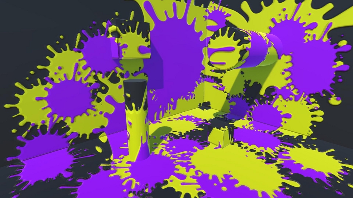
おわり
ライトマップだと解像度が足りなかったり課題は多いですが、なにかに使えそうだなと思いました。あと、この方法だと塗った面積の計算もラクラクです。


今回は実装しませんでしたが、自作プロジェクターにデプスシャドウを実装すれば「遮蔽されたオブジェクトの後ろはインクが塗られない」といった表現も可能になります。
追記
デプスシャドウも実装してみました。