Unityのみでプロジェクションマッピングを行うときに画面をマスクすることがあるのですが、べジュ曲線でマスクできると便利だな!と思って作ってみました。
べジュ曲線とは
ベジェ曲線 - Wikipedia を参考にイメージをUnityのuGUIで再現してみました。赤い点が曲線を描いています。
コード
public class Emulate : MonoBehaviour
{
    [SerializeField]
    RectTransform m_Point0;

    [SerializeField]
    RectTransform m_Point1;

    [SerializeField]
    RectTransform m_Point2;

    [SerializeField]
    RectTransform m_Point3;

    [SerializeField]
    RectTransform m_Point4;

    [SerializeField]
    RectTransform m_Point5;

    [SerializeField]
    RectTransform m_Point6;

    [SerializeField]
    RectTransform m_Point7;

    [SerializeField]
    RectTransform m_Point8;

    [SerializeField]
    RectTransform m_Point9;

    [SerializeField]
    RectTransform m_Line0;

    [SerializeField]
    RectTransform m_Line1;

    [SerializeField]
    RectTransform m_Line2;

    [SerializeField]
    RectTransform m_Line3;

    [SerializeField, Range(0f, 1f)]
    float m_NormalizePosition;

    [SerializeField, Range(1, 10)]
    int m_Speed = 1;

    private void Update()
    {
        m_NormalizePosition = Time.time / m_Speed % 1f;
        Draw();
    }

    private void OnValidate()
    {
        Draw();
    }

    private void Draw()
    {
        m_Point4.position = Vector3.Lerp(m_Point0.position, m_Point1.position, m_NormalizePosition);
        m_Point5.position = Vector3.Lerp(m_Point2.position, m_Point3.position, m_NormalizePosition);
        m_Point6.position = Vector3.Lerp(m_Point1.position, m_Point2.position, m_NormalizePosition);
        m_Point7.position = Vector3.Lerp(m_Point0.position, m_Point6.position, m_NormalizePosition);
        m_Point8.position = Vector3.Lerp(m_Point6.position, m_Point3.position, m_NormalizePosition);
        m_Point9.position = Vector3.Lerp(m_Point7.position, m_Point8.position, m_NormalizePosition);

        DrawLine(m_Line0, m_Point1, m_Point2);
        DrawLine(m_Line1, m_Point0, m_Point6);
        DrawLine(m_Line2, m_Point6, m_Point3);
        DrawLine(m_Line3, m_Point7, m_Point8);
    }

    private void DrawLine(RectTransform l, RectTransform a, RectTransform b)
    {
        var vec = b.position - a.position;
        l.position = Vector3.Lerp(a.position, b.position, .5f);
        l.rotation = Quaternion.FromToRotation(Vector3.up, vec.normalized);
        l.sizeDelta = new Vector2(2, vec.magnitude);
    }
}
note
        m_Point4.position = Vector3.Lerp(m_Point0.position, m_Point1.position, m_NormalizePosition);
        m_Point5.position = Vector3.Lerp(m_Point2.position, m_Point3.position, m_NormalizePosition);
        m_Point6.position = Vector3.Lerp(m_Point1.position, m_Point2.position, m_NormalizePosition);
        m_Point7.position = Vector3.Lerp(m_Point0.position, m_Point6.position, m_NormalizePosition);
        m_Point8.position = Vector3.Lerp(m_Point6.position, m_Point3.position, m_NormalizePosition);
        m_Point9.position = Vector3.Lerp(m_Point7.position, m_Point8.position, m_NormalizePosition);
Lerpがいっぱい出てきます。補間を繰り返すことで表現できるようです。
Vector Graphicsを使う
上記で曲線は描けるようになりましたがパス内を塗ったり、画像に保存するのは大変そうです。調べてみると「Vector Graphics」というパッケージをUnityが作成していました。SVGをインポートできるようになるパッケージのようですが、ベクターファイルを操作するAPIも含まれているみたいです。今回はこのAPIを使ってみます。
Vector Graphicsをインポート
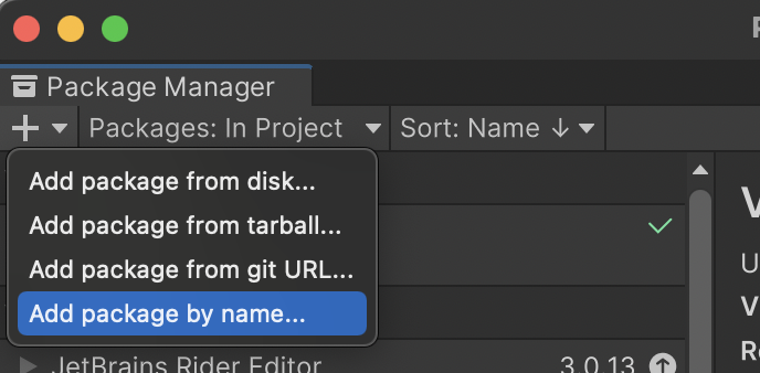
記事を書いてる現在ではパッケージマネージャーからはインポートできませんでした。Previewパッケージを有効にしても出てきません。以下の記事によるとExperimentalパッケージというのに分類されるみたいでした。
「com.unity.vectorgraphics」を指定するとインポートできました。
Vector Graphicsの使い方を探す
以下の記事で大体の使い方を知ることができました。いくつか引用させていただきます。
こちらのマニュアルも参考にしました。
memo
上記マニュアルには「Path」や「IDrawable」クラスなどが出てきますがインポートしたパッケージには含まれていなく「Shape」クラスになっていました。参考にしつつ使ってみます。
Vector Graphicsでメッシュやスプライト・画像を作るまで
❶Sceneデータを作る
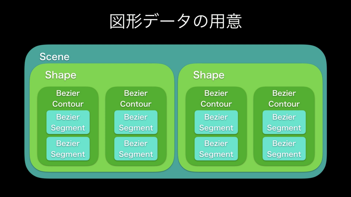
実際には以下のようになっていました。
- SceneがあってRootとしてSceneNodeを保持。
- SceneNodeはSceneNodeを子として複数持てる。
- SceneNodeはShapeを子として複数持てる。
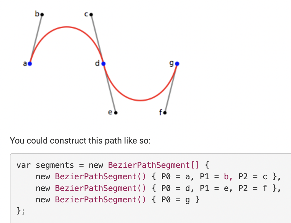
- ShapeはBezierContourを子として複数持てる。Contourは「輪郭」という意味。
- BezierContourはBezierPathSegmentを複数持てる。これが先ほどのP0やP1やP2といった点の位置データ。
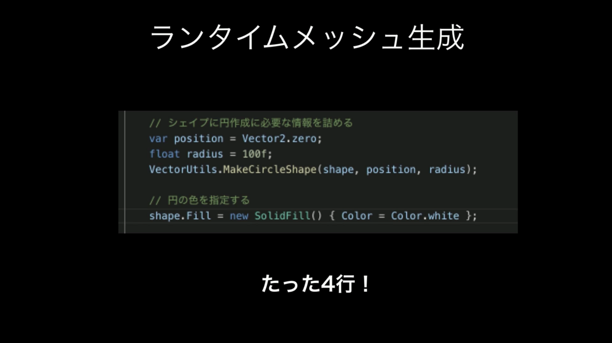
BezierPathSegmentを作ってくれるユーティリティーもありました。位置や大きさを指定して、単純な円や四角や線を作成できます。
VectorUtils.Make***
❷Sceneデータをジオメトリに変換する
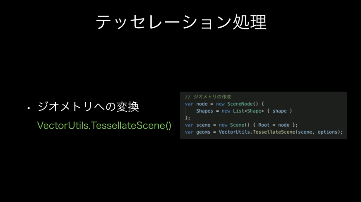
VectorUtils.TessellateScene
❸ジオメトリをメッシュやスプライトに変換
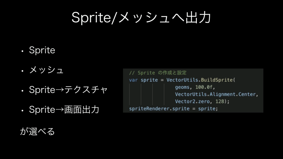
VectorUtils.FillMesh
VectorUtils.BuildSprite
❹スプライトを画像に変換
テクスチャに書き出すかマテリアルに直接渡します。
VectorUtils.RenderSpriteToTexture2D
VectorUtils.RenderSprite
エディタを作る
なんとかしてP0・P1・P2を設定できればよさそうなので作ります。Illustratorを参考にuGUIで作成しました。
反映する
作ったエディタからBezierContourを作成していろいろVectorUtilsに渡せばメッシュや画像を作ってくれます。P0・P1・P2といったデータの並び方がよくわからなかったので、以下を参考にコンバートしました。
using System.Collections;
using System.Collections.Generic;
using Unity.VectorGraphics;
using UnityEngine;

public class BezierEdit : MonoBehaviour
{
    // VectorUtils.TessellateSceneで使うオプション
    static readonly VectorUtils.TessellationOptions TessellationOptions = new VectorUtils.TessellationOptions()
    {
        // Tessellationの細かさ
        StepDistance = .1f,
        // 以下はデフォルト値
        MaxCordDeviation = float.MaxValue,
        MaxTanAngleDeviation = Mathf.PI / 2.0f,
        SamplingStepSize = 0.01f
    };

    // ここはいい感じに作る
    [SerializeField]
    UIBezierEdit m_UIBezierEdit;

    // スプライトのレンダリング先
    [SerializeField]
    SpriteRenderer m_SpriteRenderer;

    Scene m_Scene;

    private void Awake()
    {
        // Shapeを準備
        var shape = new Shape()
        {
            // ここをエディタで更新する
            Contours = new BezierContour[] { new BezierContour() },
            // 塗り方
            Fill = new SolidFill()
            {
                Color = Color.green,
                Mode = FillMode.OddEven
            }
        };

        // Sceneを準備
        m_Scene = new Scene()
        {
            Root = new SceneNode()
            {
                Shapes = new List<Shape>() { shape }
            }
        };
    }

    private void Update()
    {
        // 変更があれば再構築
        if (m_UIBezierEdit.hasUpdate)
        {
            BuildSprite();
        }
    }

    void BuildSprite()
    {
        // エディタからSegmentsを更新
        m_Scene.Root.Shapes[0].Contours[0].Segments = m_UIBezierEdit.ToSegments();

        // ジオメトリ作成
        var geoms = VectorUtils.TessellateScene(m_Scene, TessellationOptions);

        // ジオメトリからスプライト作成
        m_SpriteRenderer.sprite = VectorUtils.BuildSprite(geoms, 1, VectorUtils.Alignment.SVGOrigin, Vector2.zero, 128);
    }
}
note
// VectorUtils.TessellateSceneで使うオプション
static readonly VectorUtils.TessellationOptions TessellationOptions = new VectorUtils.TessellationOptions()
{
    // Tessellationの細かさ
    StepDistance = .1f,
    // 以下はデフォルト値
    MaxCordDeviation = float.MaxValue,
    MaxTanAngleDeviation = Mathf.PI / 2.0f,
    SamplingStepSize = 0.01f
};
ジオメトリを作成する時のオプションです。StepDistanceは分割する数なのでパフォーマンスに影響します。小さすぎると曲線がガタガタになるので、いい感じの値にしました。
// Shapeを準備
var shape = new Shape()
{
    // ここをエディタで更新する
    Contours = new BezierContour[] { new BezierContour() },
    // 塗り方
    Fill = new SolidFill()
    {
        Color = Color.green,
        Mode = FillMode.OddEven
    },
};

// Sceneを準備
m_Scene = new Scene()
{
    Root = new SceneNode()
    {
        Shapes = new List<Shape>() { shape }
    }
};
データの準備をしています。ややこしいです。
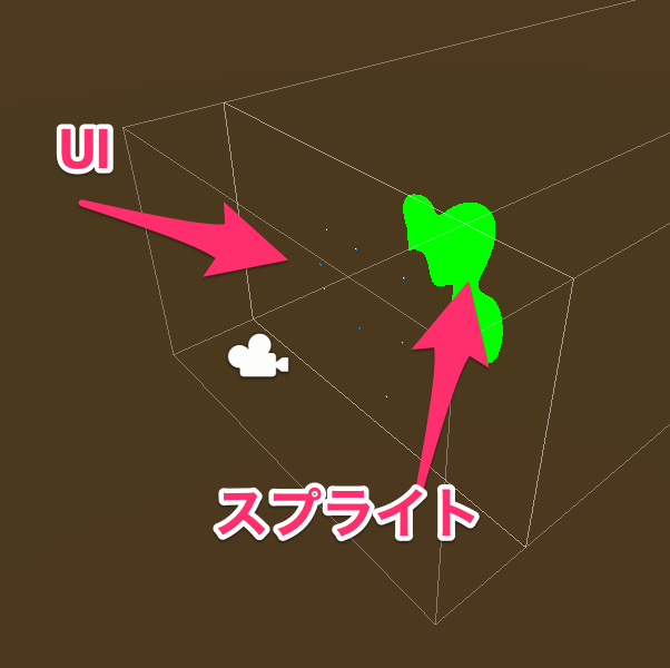
// エディタからSegmentsを更新
m_Scene.Root.Shapes[0].Contours[0].Segments = m_UIBezierEdit.ToSegments();

// ジオメトリ作成
var geoms = VectorUtils.TessellateScene(m_Scene, TessellationOptions);

// ジオメトリからスプライト作成
m_SpriteRenderer.sprite = VectorUtils.BuildSprite(geoms, 1, VectorUtils.Alignment.SVGOrigin, Vector2.zero, 128);
エディタの点の位置情報からスプライトを作成しています。
線を描く
Shapeの中身を変更します。PathPropsを指定すると線を描けるようです。Fillも一緒に指定すれば線も塗りも描画できます。
// Shapeを準備
var shape = new Shape()
{
    // ここをエディタで更新する
    Contours = new BezierContour[] { new BezierContour() },
    // 線の描き方
    PathProps = new PathProperties()
    {
        Stroke = new Stroke()
        {
            Color = Color.green,
            HalfThickness = .05f
        }
    }
};
マスクにする
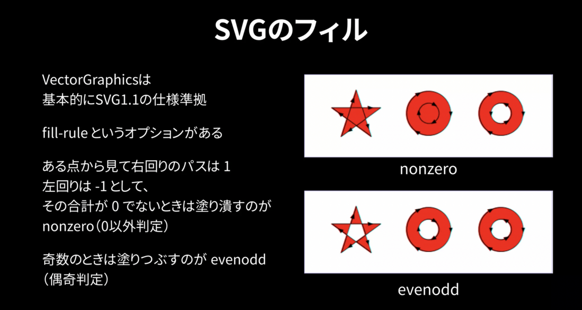
マスクしたいので黒い画像をパスで抜く必要があります。SVGの仕様とくり抜き方は以下を参考にしました。以下変更点です。
// スクリーンサイズとカメラの大きさを合わせる
m_EditorCamera.orthographicSize = Screen.height / 100f / 2f;

// 四角い輪郭を準備
var size = new Vector2(Screen.width / 100f, Screen.height / 100f);
var rect = VectorUtils.BuildRectangleContour(new Rect(-size / 2f, size), Vector2.zero, Vector2.zero, Vector2.zero, Vector2.zero);

// Shapeを準備
var shape = new Shape()
{
    // ここをエディタで更新する
    Contours = new BezierContour[] { rect, new BezierContour() },
    // 塗り方
    Fill = new SolidFill()
    {
        Color = Color.black,
        Mode = FillMode.OddEven
    },
};
画面を覆い尽くす黒い四角を登録しています。
// エディタからSegmentsを更新
m_Scene.Root.Shapes[0].Contours[1].Segments = m_UIBezierEdit.ToSegments();
2つ目の輪郭に登録することでくり抜いています。
おわり
memo
最終的な結果を画像として保存して、ポストエフェクトなどでマスクを適応するといいと思います。
VectorUtils.RenderSpriteToTexture2D
他に参考にさせていただいた記事
ありがとうございます。